Introduction
Designing a voltage divider may seem straightforward, involving a few resistors and basic calculations. However, ensuring its reliability over lifetime and operating conditions can pose a challenge when conducting a worst-case analysis. Voltage dividers, integral to circuits like sensors and amplifiers, are sensitive to component tolerances, temperature shifts, and in combination with filtering, even to supply voltage fluctuations (dc-bias).
In this blog post, I want to cover different aspects of voltage divider design.
As worst-case circuit analysis (WCCA) was not in particular focus or even taught during my studies, and might be left untouched in most courses, I want to give some insides. Here my agenda!
- The basic voltage divider
- Effect of tolerances on the voltage divider ratio
- Voltage Divider + Low Pass Filter (Anti-Aliasing Filter)
- Effect of the input voltage range on the 3dB-corner frequency
The basic voltage divider
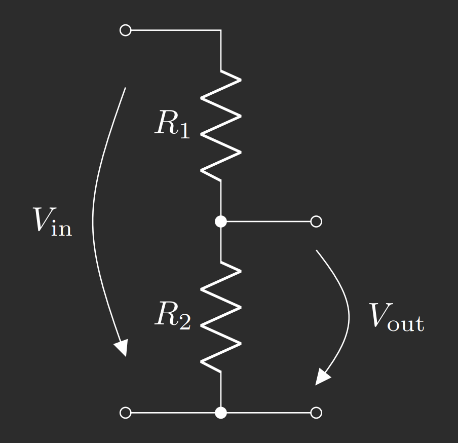
Consider the circuit shown in Figure 1 below. An input voltage \(V_\text{in}\) applied across two resistors \(R_1\) and \(R_2\). The output voltage \(V_\text{out}\) is considered as the partial voltage developing across \(R_2\).

The voltage divider ratio \(A_\text{div}\) can be derived as follows.
$$\begin{equation}V_\text{out} = I_\text{in} \cdot R_2\end{equation}\tag{1}$$
with
$$I_\text{in} = \frac{V_\text{in}}{R_1 + R_2}\tag{2}$$
gives
$$A_\text{div} = \frac{V_\text{out}}{V_\text{in}} =\frac{R_2}{R_1 + R_2}\tag{3}$$
Effect of tolerances on the voltage divider ratio
So far, so easy! Now we’re going to include resistor-tolerances. Just by taking a look at the voltage divider ratio it becomes obvious that the worst-case ratios are achieved when \(R_1\) and \(R_2\) are at their maximum / minimum tolerance, respectively. Extending (3) to include tolerances we get the max. and min. ratio \(A_\text{div,max}\) and \(A_\text{div,min}\).
$$A_\text{div,max} = \frac{R_2(1+e_\text{R2})}{R_1(1-e_\text{R1}) + R_2(1+e_\text{R2})}\tag{4}$$
$$A_\text{div,min} = \frac{R_2(1-e_\text{R2})}{R_1(1+e_\text{R1}) + R_2(1-e_\text{R2})}\tag{5}$$
A different approach is to use error propagation. This is done by deriving the total differential of \(A_\text{div}\) to get the absolute error \(\Delta A_\text{div}\).
$$\Delta A_\text{div} = \left|\frac{\partial A_\text{div}}{\partial R_1}\right| \cdot \Delta R_1 + \left|\frac{\partial A_\text{div}}{\partial R_2}\right| \cdot \Delta R_2\tag{6}$$
$$\Delta A_\text{div} = \frac{R_2}{R_1^2+R_2^2} \cdot R_1 e_\text{R1} + \frac{R_1}{R_1^2+R_2^2} \cdot R_2 e_\text{R2}\tag{7}$$
$$\Delta A_\text{div} = \frac{R_1R_2}{R_1^2+R_2^2} (e_\text{R1} + e_\text{R2})\tag{8}$$
$$A_\text{div,max/min} = A_\text{div} \pm \Delta A_\text{div}\tag{9}$$
When inspecting (8) it becomes obvious that both resistor tolerances add equally to the error of the divider ratio \(A_\text{div}\). Since \(R_2\) typically is a single resistor and \(R_1\) is often a resistor ladder, the cost-effective approach is to improve on \(R_2\) tolerance first.
Voltage Divider + Low Pass Filter (Anti-Aliasing Filter)
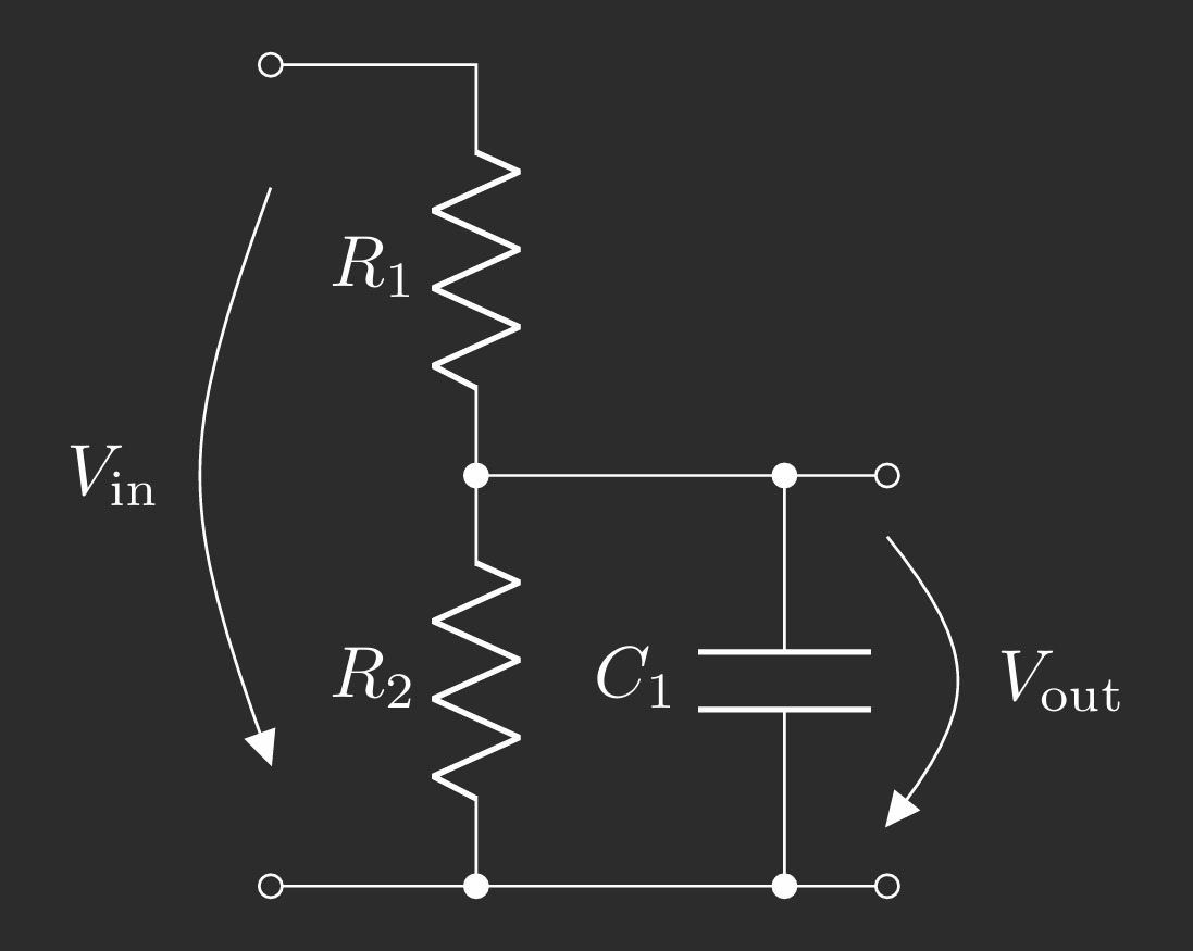
In general, the voltage divider, specifically \(R_2\), is connected in parallel to a capacitor \(C_1\) (figure 2, todo) to filter noise and/or ac/transient signals not of interest for the application-specific circuit.

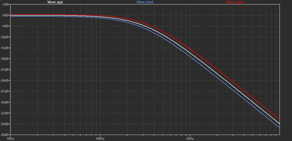
Of course, \(C_1\) is subject to tolerances as well. This poses the challenge, that you can’t consider a single ac filter response anymore. Instead you’ll get a window, as shown below.

Knowing about the tolerance-dependent ac response of the voltage divider, how to deal with it in your application?
Effect of the input voltage range on the 3dB-corner frequency
Section still under construction !
Conclusion
In this post I introduced to the worst-case circuit analysis (WCCA) of the voltage divider. It was shown how to calculate min. and max. voltage divider ratio, and that tolerances of resistors add equally to the overall dc error it. Based on Eq. (8) it was interesting to see, that \(R_2\) (typ. a single resistor) can be changed to improve tolerances in the most cost-effective way.